Microphone calibration tutorial - using REW
Detailed instructions for producing microphone calibration files from substitution measurements in widely popular, free REW acoustic measurement software.

Why calibrate microphone yourself?
There are many reasons to perform your own (DIY) microphone calibration, for example:
- To create 90 degree calibration file for a high-end reference microphone that only comes with free-field (0 degree) calibration.
- To calibrate any cheap microphone to match a reference microphone (especially if cheap microphone comes with at-least generic calibration file).
- To build an array of several cheap microphones those are all calibrated towards one reference microphone (instead of buying multiple expensive microphones).
- To cross-check accuracy of your reference microphones (faster and cheaper than sending microphones for a laboratory re-calibration).
- To confirm or improve calibration of an old measurement microphone that was not re-calibrated for a long time.
Note: calibration laboratories should be able to perform calibration on most microphone models - simple solution to maximize precision of any microphone and receive calibration certificate as well.
Introduction about measurement microphones
Importance
of measurement microphone for audio system tuning is comparable to importance of
a ruler and bubble level for mounting a shelf. Without a measurement microphone
audio goes from an engineering problem into a very rare skill domain. Even if
microphone is used rarely; instrument should be precise enough for the job – ideally
it should be accurate to about +/- 0.5 dB or better.
Instrument
grade measurement microphones are low-volume devices that are expensive to manufacture, but reality is that most cheap, flawed omni-directional microphones can
be equalized with a calibration file (correction curve) to perform effectively
as good as professional microphone for most measurements (just like measuring
tape is accurate enough for most tasks at home).
Cheap microphone
with accurate calibration file works great for:
- Sound system tuning and room-correction.
- Most room acoustics measurements.
- Frequency response measurements (on component level).
Instrument
grade microphones are needed:
- To
use microphone without calibration files – mostly for convenience or phase
response.
- For
measurement stability over years and temperatures (to some degree professional
equipment is more robust, even if it is often re-calibrated).
- To
measure very high SPL (cheap microphones usually are not optimized for extreme
SPL).
- To
measure very low SPL (low noise floor requires large diaphragm microphones).
- For specialized scenarios (boundary mics, pressure mics, heat resistant, etc.)
Calibration is the problem – consumer grade measurement
microphones are usually calibrated fast and cheap – in bulk, in ways which
would not be acceptable for any certified instrument calibration laboratory.
Therefore even if consumer microphone comes with a calibration file, unless it
was re-calibrated by an independent laboratory, the manufacturer calibration files are not great – calibration is usually
off by several dB at higher frequencies (search the internet for numerous
reviews with comparison measurements between microphones).
The good news is – if one reference microphone and one OKish-speaker are available, then a reasonably good calibration can be done fast without any lab or advanced skills.
Good to know:
- At low frequencies (below 100 or even below 400 Hz) microphone orientation (usually facing forward-0-degrees or up-90-deg) and reflections from microphone holder do not matter. Microphone could even point in the opposite direction from the speaker and measurement will be the same. But...
- At low frequencies (below 100 or even below 400 Hz) in small rooms, room modes make exact position of microphone capsule very significant for accuracy/repeatability.
- At high frequencies small things like microphone holder attachment and the cable can introduce reflections that impact measured frequency response - try to keep all mounting details realistic and consistent between microphones. (to eliminate these effects, in calibration labs, microphones are mounted in near flawless holders - not in a typical microphone stand)
- All of these effects can easily be tested by repeating the measurement and varying the position, attachments, etc. OR it is just easier to be precise and consistent.
Overall the objective is: to verify and improve calibration of one
measurement microphone against another, reference microphone.
Calibration Steps
- Measure one speaker with both REFerence microphone(s) and microphone that needs to be
re-calibrated - "DUT" - Device Under Test.
- Use substitution of
microphones in front of the same speaker: each microphone is
placed as-precisely-as-possible (precision
within a couple of millimeters) in the same spot, one at a time. (People often ignore this and place microphones even several centimeters off
from one another which is a Bad idea)
- Seriously be precise! Use alignment laser or another trick for alignment; make an effort to use exactly the same microphone holder to keep all reflections identical; go far away from the microphone to not act as random-human-acoustic-reflector. It should be practical to be exact down to a couple of millimeters – it does not cost extra to be precise, while room modes and various reflections can impact your calibration result.
- (There are several YouTube videos of people doing microphone calibration measurements with REW where the physical microphone substitution accuracy is poor, but the overall procedure is usually the same.)
- Speaker should be physically small, coaxial or a "full-range" driver. It does not need to have flat frequency response, just needs to have enough output at all relevant frequencies to give enough dynamic range versus ambient noise and microphone self-noise. Try to avoid speakers that have narrow dips or peaks in the response (from port cancellations, resonances, etc.).
- Note: calibration will only be valid at frequencies that speaker can reproduce (it is rare to get a speaker with good lower bass output that is otherwise compact and full-range). This is OK if the microphone already has low-frequency calibration (low frequencies are less likely to be incorrectly calibrated by manufacturer). Alternatively calibration can be done in 2 steps, where bass calibration is done with a subwoofer.
- Use typical REW Measurement Sweep
at 48 or 44.1 kHz (perhaps using longer sweep length 512K, and/or a few repetitions).
- Measured speaker should be reasonably warm - if first measurement is done on a cold speaker and the rest on a speaker after some sweeps - the speaker may have a bit different frequency response.
- Check maximum THD distortion in the measurement.
- Do not use frequencies where THD exceeds > 3-5%. If distortion is high - either the speaker is pushed too loud or the speaker cannot reproduce so low bass frequencies (i.e. speaker does not produce enough output at a given frequency to overcome ambient noise).
- Consider adjusting sweep
frequency range to skip un-usable frequencies. No inaccurate data saved
means no risk of accidental use.
- + optimize placement to
reduce impact of reflected sound (no strange shelfs, furniture corners or other objects that cause strong reflections near speaker and microphone). Avoid comb-filtering from multiple
drivers playing the same frequencies. Leave enough distance for sound of
multiple drivers to integrate (do not put microphone too close to the speaker).
- Ideally measurements would be done in anechoic chamber, but without specialized lab, try to pick location with as much as possible free space around the microphone.
- (Optional, but not recommended) to counteract room reflections it is possible to apply "IR Windows" to all measurements. Windowing also reduces bass frequency measurement accuracy, so it is a tradeoff. (Optimal windowing is not trivial, but for a start settings could be frequency dependent window with 15 cycles, Tukey 0.25)
- Apply light smoothing on the measurement data, for example 1/48. (note, smoothing and windowing will be used in the Trace arithmetic.)
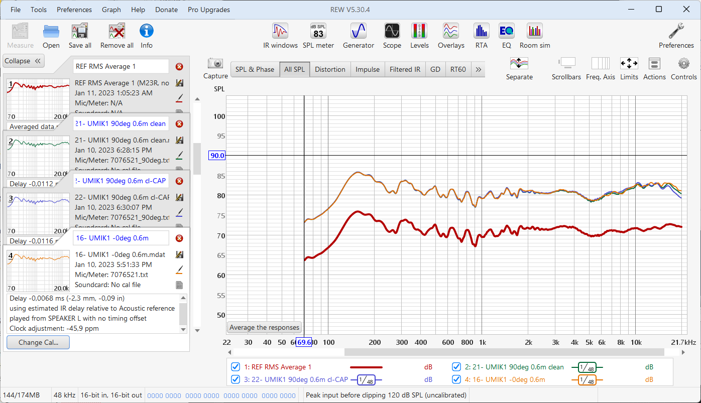
Three initial measurements of UMIK1 in 2 orientations (plus 1 with a wind protector cap), without DUT calibration files compared to REFerence measurement (already averaged from multiple REF measurements). - Alternatively, smoothing may be redundant if "IR Windowing" is used.
- Apply OLD calibration file to the DUT measurement data (if there is any suitable generic "OLD" calibration file available).
- Note: it is possible to add or replace microphone calibrations for each measurement in REW at any point. (In fact the calibration file may already be applied if it was not removed when the measurement was taken in REW.)
Loading of calibration file UMIK1 measurements with OLD manufacturer calibration files applied. Note that SPL difference is because REFerence mic was not SPL calibrated on the analog interface. - Run “RMS Average” on the DUT data (the same as “Average the responses”) - to both bake-in the old calibration file and remove phase information in the DUT data.
- Important to hide all unrelated data using checkboxes on the "All SPL" tab legend (otherwise averaging will include all visible measurements).
- If there are several takes of the same measurement – now is the time to show/select all relevant repeated measurements and “RMS Average” them into one.
- When done correctly new measurements with “Magnitude data produced from…” will appear and the list (in case of no repeated measurements).
Baking-in calibration files and dropping phase by averaging. - Same steps for the REFerence data:
- Apply calibration files - even the best microphones still benefit from their correction data (except in rare special scenarios). Then,
- Run "RMS Average" on the REFerence microphone data (to bake-in the calibration file, remove phase information and optionally average multiple measurements).
- Note: if possible, take an average of several REFerence microphones - no microphone is perfect, so average of multiple top-quality microphones is better than any single one of them.
- Use "Align SPL..." on the averages of DUT and REF.
- In case of calibrating miniDSP UMIK use "Align SPL" to 0dB at 1 kHz with 0 or 1 octave span (because UMIK calibration files are always about 0dB at 1000 Hz).
- For other cases, choose alignment parameters that make the most sense (usually using midrange frequencies within 250 to 2000 Hz, because at high frequencies reflections make the data less consistent between microphones).
Aligning SPL. - Use "Trace arithmetic" ==> "A/B" to divide: averaged DUT data / REFerence data. The result is "OFFSET correction".
A-over-B operation. - Load OLD calibration file as a measurement (using File => Import frequency response).
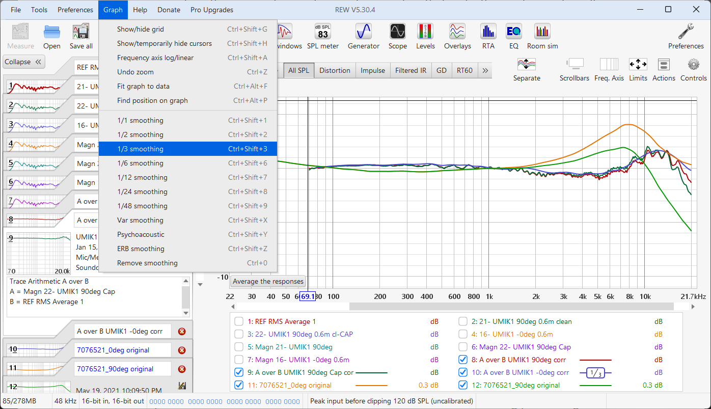
- Apply 1/3 (or 1/6) smoothing on the "OFFSET correction" to make it about as detailed as the OLD calibration curve. (The smoothing will be used in the Trace arithmetic.)
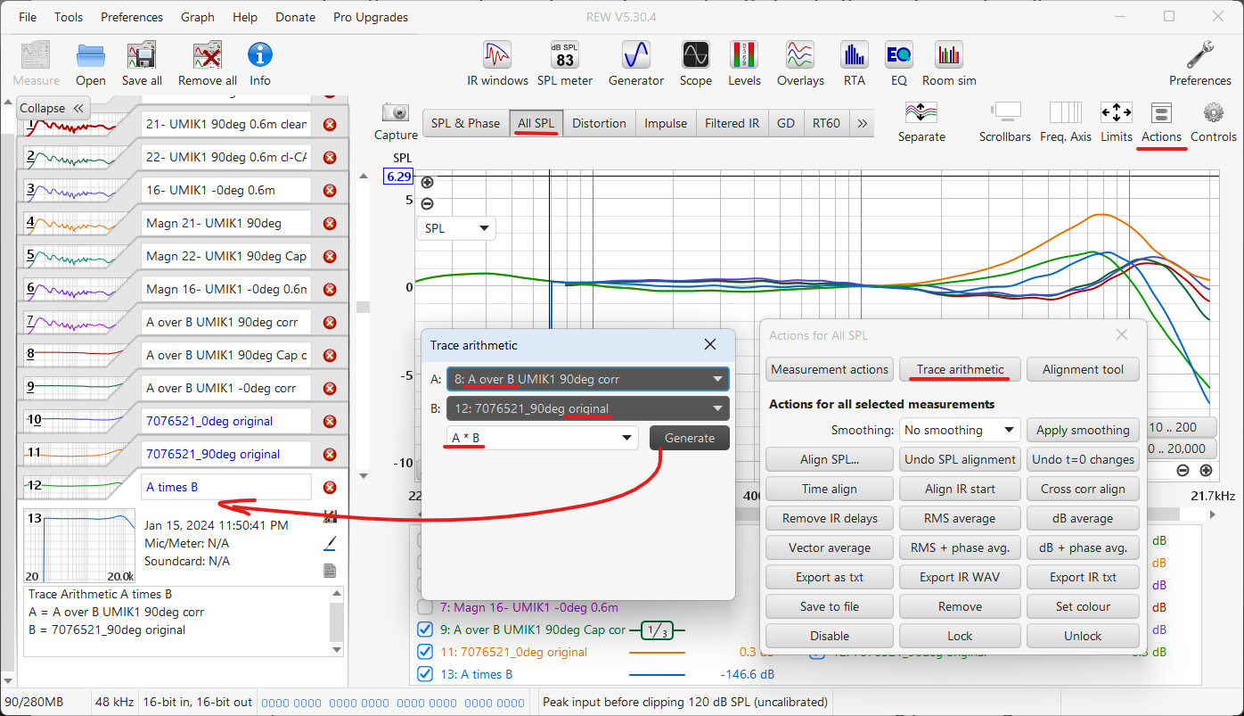
Apply smoothing on A-over-B. - Use "Trace arithmetic" ==> "A*B" to multiply: smoothed OFFSET correction * OLD calibration file. The result is "the initial NEW calibration". (Note, the input data has no phase and there is no need to do SPL alignment before multiplication in this case).
New calibration A-times-B. - (if there are 2 calibrations to join - "OLD & NEW" calibrations /or "Low & High" frequency calibrations) Choose a Splicing/joining point between OLD calibration curve and the new.
- Main calibration measurement often does not include bass frequencies (if measured speaker is small), therefore it is logical to either leave bass calibration from the OLD calibration file OR make one more calibration measurement with a subwoofer which could produce the bass-part of the calibration for a microphone that does not have any OLD calibrations.
- Check: it might work to splice of OLD and NEW curves with minimal or no SPL adjustment of the NEW calibration. (From previous steps the OLD and NEW lines should already be approximately aligned around 1000 Hz)
- Splicing is best done at a frequency lower < 1100 Hz where the OLD and NEW files smoothly meet (curves gradually meet or cross) – smooth transition is the goal. + The data after splicing should look reasonable (this will be your correction).
- Write down the approximate frequency and dB value for splicing after exporting (easiest to put a data cursor in the splicing point and take a screenshot of the information).
Screenshot to remember the chosen Splicing point (each case is different - use own judgement to pick a good point). - NOTE: if the difference between OLD and NEW calibration is less than ~0.5 dB – then consider to not change the OLD calibration at all. Differences less than 1 dB could easily be caused by measurement error and it may be wise to keep using the OLD calibration file.
- (only if necessary) Manually align SPL of the NEW calibration (do not change the OLD) to match OLD calibration and press "Add Offset to data". Alignment is done at a frequency where you decide to join the OLD and NEW calibration data together.
- (for some cases it is makes sense to use "Align SPL..." function on the NEW curve to match the frequency and dB value of the splicing point on the OLD curve).
- Then, do the manual "SPL offset" in fully zoomed in view by going to "Measurement actions" and dialing in "SPL offset" value.
Manual SPL alignment (if needed & only on NEW calibration curve). - Export NEW calibration Input as text with 48PPO and NO-additional smoothing (smoothing should already be sufficient from previous operations).
Export of NEW calibration input data (48PPO). - Splice the data: copy only the relevant frequency-SPL rows from the exported NEW calibration text file into the original OLD calibration text file using basic text editor.
- First make a copy of the OLD calibration file to modify (name it for example "NEW Final calibration")
- Add-remove relevant rows from the exported NEW calibration Input file to get a smoothly increasing frequency data in the final calibration file.
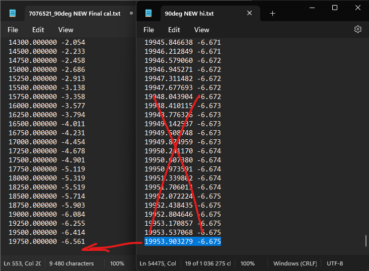
Actual Splicing point selected for smoothly changing numbers (therefore this final calibration will use values from OLD calibration up to 77 Hz, but above 78 Hz all values are replaced by NEW data). - For miniDSP UMIK microphones it may be useful to adjust the sensitivity value inside calibration file to account for the correction value at 1000 Hz. Original, OLD calibration file has ~0 dB level at 1000 Hz, so any change from that needs to be compensated in the sensitivity value.
- Even better if it is possible to use special microphone level calibrator to more precisely calibrate sensitivity towards a measured 94dB, 1000 Hz reference signal
- Note - this specific UMIK1 had very accurate SPL calibration from manufacturer - within 0.1 dB from calibrator reference (may not be indicative of other samples or models).
- Check that there are values all the way up to 20 kHz (or higher).
- In case the exported 48PPO correction data stops below 20 kHz:
- export 2nd text file with "Use resolution of measurement" setting to include the highest available frequency (48PPO setting drops some data at the extremes of the frequency range).
Export of additional highest frequency data point (only if normal 48PPO export did not contain data for at least 20000 Hz). - Then copy just the last row out of this "high-resolution" file into the Final calibration text file.
Adding missing 20000 Hz data point. - Consider to round the top frequency up. To have defined "20000.0" microphone correction point.


Comments
Post a Comment